

2J1 was superseded by the 2J2/9 in July 2010. Thousand of 2J1 units have been sold worldwide since it was introduced in January 2007. This page describes the original 2J1 and contains the Technical Reference for 2J1. Tech Edge actively supports the 2J1 as it does other models now no longer in production.
2J1 was Tech Edge's first economy, single-channel, entry level wideband controller (Our first fully digital wideband controller was the 2A0 DIY controller introduced in July 2003). 2J1 is lower cost because it has slightly simpler circuitry, has a fixed cable to the sensor, and works only with the Bosch 4.2 LSU sensor (either 7057 or newer 7200). It retains many of the features of other Tech Edge units including inbuilt analogue channel capture and RPM capture. Our 2C0 is a more accurate (12 bit hardware DAC output) but more expensive small controller.
)
|
Tech Edge 2J1 WBo2 Features
|
Please note: 2J1 has a 1 m (approx 3') cable to the sensor. It has a 1 m power cable, and a 1 m RS232 and data cable. Sensor cables are around 0.5 m long so the distance from the sensor to the 2J1 is about 1.5 m and the distance from the sensor to the end of the power cable is 2.5 m (over 8'). Our displays typically have 1.8 m cables so the display can typically be placed 3.3 m (over 12') from the sensor. This means our standard 2J1 and displays will work in most vehicles.
We do NOT sell a 2J1 with a longer cable (ie. one size fits all!).
But, we can customise 2J1 for purchase quantities of 25+ (lead times apply).
(*) The older (and more expensive, but no better) 6066 sensor will work with the 2J1 (Auto-cal range allows this for most 6066 sensors)
but the connector end must be replaced - we do not do this for individual orders,
but it can be arranged for larger orders (25+). We don't recommend, nor support, this modification!
2J will NOT work with the LSU 4.9 sensors.
The latest 2J2/9 unit is the updated version of the 2J1. Here are the major differences:
1. 2J2/9 has no fixed cables. Longer sensor cable (about 2 metres 2J2/9 to sensor tip).

2. 2J2/9 mutliple sensors sopported (LSU 4.2 and the newer LSU 4.9).
3. 2J2/9 removable screw-header - no wire loom for connection of inputs and outputs.
The rest of this document is the user manual for 2J1.
Please note that, although 2J1 has been superseded by the 2J2/9, this documentation is subject to change based on your feedback.
2J1 differs from other Tech Edge wideband units in not having a removable cable between the sensor and controller. It's also designed to be installed in a cool part of a vehicle's engine bay (but remember the case is ABS plastic, it will melt near an exhaust pipe). Even installed underneath a vehicle is possible, although direct exposed to the elements is not recommended. 2J1 features a conformally coated PCB for protection. Other Tech Edge wideband controllers use pluggable screw terminal connectors but these may admit dust and moisture into the casing, and to keep down the cost, we opted to use flying leads instead.
The various I/O connections are described below. The connection diagram are to the right, along with wire colours to aid you in connecting the 2J1 to your vehicle. Just remember not to short out any of the unused wires against battery voltage or GND.
)
On the top of the case (with the sticker) can be found ..
The ends of the case carry the sensor cable, the power cable, the display/RS232 cable and I/O cable.
The larger grey cable is referred to as the I/O cable, and carries various inputs and outputs described below.
| GROUND - Provides a ground return for Vbatt, and a ground reference for NBsim, WBlin-, etc. Also internally connected to the SHIELD wire. | |
| USR 1 - A 0-5v Analog channel for logging sensors such as MAP & TPS. | |
| USR 2 - As per USR 2, values appear in the RS232 frame generated by the 2J1 unit. | |
| LSS Tx - An optional Low Speed Serial output (1200 baud), for connection to a future intelligent display, not currently activated in firmware. | |
| Vbatt - Provides battery voltage to remote 12 volt sensors or displays. | |
| WBlin- - Ground reference for WBlin+, should be tied to GND or close to GND as it affects WBlin+ if left floating. | |
| WBlin+ - 9.5 bit PWM-sourced Differential Wideband output. | |
| NBsim - 7.5 bit PWM-sourced programmable output, used for Narrowband sensor simulation. | |
| RPM - 12 volt compatible (COIL style) RPM pickup for logging engine revolutions. | |
| PULSE - 5 volt PULSE input for logging an additional pulse input, intended for Vehicle Speed Sensors. |
2J1 has been designed to be mounted in harsher environments than other Tech Edge wideband units, typically under vehicles and in the engine bay. As dust and moisture can be a problem in these locations, 2J1 has had a Conformal Coating applied to the PCB, greatly reducing the effects of moisture and grit, while still affording good access for repairability if necessary by allowing "solder through" the coating. 2J1 may be further protected in harsh conditions by placing it in a clear plastic bag, and using a cable tie on the opening to seal the cable entry.
2J1 comes standard with 1 metre of sensor cable, this should prove adequate to mount the 2J1 a reasonable distance from hot exhaust components for most installations. Typically it will be possible to route the sensor cable into the vehicles cabin via the transmission tunnel and shift lever boot, and mount the 2J1 inside the cabin for extra protection and convenience.
Technical Overview | Outputs | Inputs | LED Diagnostics
The 2J1 unit, without cables, weighs just over 100 grams, and the case measures 90 x 50 mm with height of 17.5 mm. Sensor, power, display, and the new I/O cable are integrated with the unit, the signals on these cables are described below.
WBlin GREEN & BLUE on I/O Cable , Wideband Output
A synthesized linear WBlin voltage is produced by the onboard microcontroller using a 10 bit A/D PWM converter (with single pole filter). We describe this as having an accuracy of 9.5 bits (rather than 10) to distinguish it from outputs on our other units that use more accurate hardware DACs. Other Tech Edge controllers use a more accurate 12 bit DAC for better performance, and this one of the major differences between 2J and other Tech Edge controllers. * Note-1: WBlin- (green) must be tied to a voltage close to GND. Failure to do this will cause WBlin+ to be undefined. 2J1's WBlin can output a maximum of 5.00 Volts and can be re-programmed. A special feature of WBlin is what we call a differential output. The WBlin+ output wire (BLUE) is the signal, and the WBlin- output wire (GREEN) is the ground reference (actually an input). This arrangement is designed to reduce the amount of noise and possible voltage offset errors seen by a device connected to WBlin. The WBlin differential output is described more fully here. WBlin can be re-programmed using the Config utility to cover any part of the AFR range from Lambda = 0.6 to free-air over the 0 to 5 Volt range. For the default mapping shown, to convert WBlin to an AFR, simply multiply the measured voltage by 2 and add 9. The advantage of a linear output is that it's easy to write a conversion function from the wideband voltage to AFR. * Note-2: Remember that WBo2 is a Lambda meter and is "calibrated" to display AFR for fuels with a stoich AFR of 14.7 (ie. "unleaded"). For other fuels that don't have a stoich value of 14.7, the x-axis (AFR) of the graph shown here should be modified. * Note-3: while the WBlin output is accurate, the Lambda data in the RS232 data frame is inherently more accurate and does not suffer from some possible sources of signal degradation that beset all analogue data. |
NBsim VIOLET on I/O Cable , Simulated Narrowband Output
A synthesized narrowband (NBsim) voltage is produced by the onboard microcontroller using an 8 bit A/D PWM converter (with single pole filter), and a 65 word lookup table. Linear interpolation improves lookup accuracy. We describe this as having an accuracy of 7.5 bits to distinguish it from outputs on our other units that use hardware DACs. The full 0 to 5 Volt output is available, but restricting the output to 0 to 1 volt reduces the number of possible steps to around 200 (~5 mV per step). The NB output is designed to be compatible with the raw output of a Bosch LSM-11 sensor. Refer to this eXcel spreadsheet for the graph of the default NBsim vs AFR. As NBsim can re-programmed it is possible to do a number of interesting things such as fooling the engine's ECU (if equipped with a NB sensor) into running richer or leaner than it would do otherwise. |
|
RJ45 Outputs - RS232RX , RS232TX , GND & Vbatt

As 2J1's major function is to measure AFR (or Lambda), the unit provides an RS232 data stream that contains digitally precise information on sensed AFR and all logged inputs. This may be connected to a PC for data logging, or to a Tech Edge digital display such as LA1 or LD02 These outputs are described in detail in the following paragraphs. Note: Pin 3/RJ45 refers to pin 3 on the 8 pin RJ45 connector. A protected and partially filtered battery voltage Vbatt is available from [pin 8]. This output is provided to power other devices such as the LA1 display or the LD02. It should only be connected to devices that will draw small currents; typically less than 100 milliamps. Excessive current consumption may cause heating of an internal dropping/protection resistor. A ground GND point [pin 5] is provided as a return for the RS232 and Vbatt connections. The RS232 signals themselves are on Rx [pin 2] & Tx [pin 3]. |

|
The 2J1's RJ45 connector carries RS232 and other signals. The unit transmits logged data on its Tx line [pin 3] and receives commands (from PC or display) and code updates from a PC on its Rx line [pin 2]. The diagram at left shows the wires within the separate (supplied) data cable and also the connections at each end. Note the pin names change from left to right - the WB unit's Tx pin transmits to the PC's Rx pin (and vice versa). [pin 5] is the shield for the Rx and Tx data lines as well as being the return data path. |
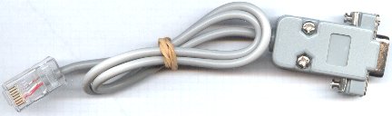
WBo2 to PC cableHere's an image of the actual RS232 cable for connection between a PC and the WB unit. The cable is used for either logging to a PC, or for re-flashing its code (under control of a PC). If you need to extend the cable then a standard straight through male-female DB9 extension cable should be used (ie. not a cross-over or null modem cable). |
|
Analogue Inputs USER1 & USER2
The BROWN and RED wires of the I/O Cable are two 0-5 Volts single ended analogue inputs (USER1 & USER2). They can be used for sampling voltages such as TPS (Throttle Position Sensor) and MAP (Manifold Absolute Pressure), but remember that the measured voltage should not exceed 5 Volts. They are not suitable for measuring pulse inputs unless the pulses have been processed by an external circuit. The USER voltages are sampled at a resolution of 10 bits at a rate determined by logging configuration parameters (default 10 sample/sec). The 2 channels have at least a 10k ohm input impedance. The 10 bit resolution means variation as small as 5 milliVolts can be detected, but in practice the noise limit sets the resolution to as low as 15 to 20 milliVolts. Note that unterminated inputs will float and may show a voltage level when not being used. Either ignore this effect or physically connect all unterminated inputs to the BLACK Ground wire. |
Pulse Inputs - RPMLO and PULSEVSS
2J1 has two PULSE channels that are captured for logging. These are separated into two inputs (RPM & VSS), with RPM being primarily intended for use with an ignition coil or tach style signal (0-12v COIL). Refer below for details of the Secondary VSS input. Diagram at right shows routing of RPM input via the Low-Pass filter that can be used to assist with installations that generate a large amount of high frequency noise on the RPM pickup. :
|
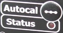
Diagnostics from the STATUS LEDThe unit has one RED Status LED that flashes while the sensor is warming up, and to indicate error conditions. Should be solid RED to indicate normal operation.
Unlocked PID : It's possible for transient conditions to cause the STATUS LED to flash OFF briefly, this is an indication of a PID unlock condition. A PID unlock is not necessarily an error, but it does indicate either very rapid changes in heating or cooling of the sensor, and/or rapid changes in the ambient air-fuel ratio. If this occurs without an explanation (such as rapid changes in throttle position) then it may be an indication of an intermittent somewhere in the wiring, or an aging sensor. Both the LD02 and the TEWBlog logger indicate these conditions. The heater PID sharp single OFF flash is shown. This condition may indicate the sensor is positioned where it is either too hot or too cool. We have information on sensor placement. Remember wideband sensors cannot cool them self, only heat!
Auto-Cal - Automatic Sensor Re-calibration)
Calibration is the process of making the unit read as accurately as possible. Calibration is required because 2J1, although we ship it calibrated to the sensor purchased for the unit, it is manufactured un-calibrated. We do this so 2J1 can work with a number of different sensor types (it is possible to change the 7057/7200 sensor connector, at the end of the cable, for another LSU 4.0/4.2 connector). Note, we don't ship 2J1 with the 6066 connector, as shown in the image at right. Additionally, each sensors is manufactured slightly differently, and calibration matches the sensor to the unit. In fact, because Bosch sensor have a neat inbuilt calibration resistor that our units work with (see image at right), once a sensor is calibrated, very good accuracy is maintained when another sensor of the same type is substituted. So, the major reason for having a calibration function is to initially calibrate the unit to a sensor, and then to account for any aging of the sensor (or control unit) that affects its calibration. The Auto-Cal function makes it easy to re-calibrate a sensor. In fact it almost makes it too easy! To explain this we need to look at how calibration works. Basically the sensor must be placed in a known concentration of oxygen (and/or fuel) and the "gain" of the controller adjusted to match the sensor's output. The sensor's environment is critical for it to calibrate correctly. We choose to place the sensor in free-air which means the sensor is directly exposed to fresh, clean, normal air that anyone could breath (ie. it is not sitting in an exhaust pipe) We make these assumptions about free-air :
If any of these conditions are significantly different, then, although the sensor will calibrate to some value, it will not be as accurate as possible. The basic risk for a sensor placed in an exhaust system, and with an Auto-Cal function, is that re-calibration could occur with the sensor in a "dirty" atmosphere. It is vitally important that any re-calibration occurs with the sensor out of the exhaust pipe
Further InformationWe update 2J1 documentation from time-to-time in response to your Feedback. Right now (see the latest update date below) we have more information to add, so if there's something you're keen to get more info on, then see the link below. You may be interested in our displays. Go here for more info. |

)
)