) 2J-OEM6 is Tech Edge's economy OEM wideband controller.
2J-OEM6 is based one the original 2J1 retail product.
2J-OEM6 is Tech Edge's economy OEM wideband controller.
2J-OEM6 is based one the original 2J1 retail product.
 OEM6 is not a stand-along controller and requires regulated power (5 Volts)
as well as access to full battery power for sensor heater operation.
It is supplied an assembled and tested board as described below.
OEM6 is not a stand-along controller and requires regulated power (5 Volts)
as well as access to full battery power for sensor heater operation.
It is supplied an assembled and tested board as described below.
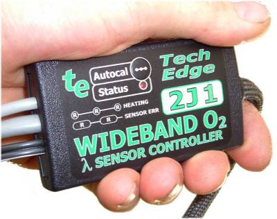
2J-OEM6's parent device (shown at right), the 2J1, is Tech Edge's
low cost, single-channel, entry level wideband controller.
The 2J design uses simpler circuitry compared to other Tech Edge units.
The number 6 in OEM6 has no particular significance - it just happend to be part of the name of our original OEM6 customer's module.
)
)
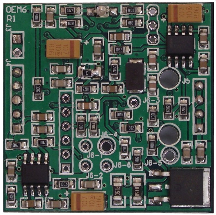
2J-OEM6 LSU Controller - BrieflyClick on these links for large images of the OEM6 module: top overlay, top photo, bottom overlay, bottom photo, engineering diagram (PDF). OEM6 is approximately 38 x 38mm (around 1.5" square). It is designed to be soldered directly to a main PCB, or plugged into two in-line headers (J4 & J5, 0.1" pitch) at opposite sides of the PCB. The board requires a regulated low current +5 Volt supply to power the processor (such as from a generic 7805 regulator) The heater of the wideband sensor requires a +12V supply with a start up current of up to 3A (where the terminal voltage must NOT fall below 10.5V at an average current 3A for up to 10 seconds during startup). After startup heating, the heater typically runs continuously at an average current of less than 1A (at 12 Volts, but less at higher voltages). The module's absolute maximum operating voltage is 19.5V. The module will turn off if the minimum and maximum voltages are not maintained. The module, unlike other units we sell, cannot tolerate reverse battery connection and has no heater voltage spike protection. The sensor is connected to 6 points on the PCB (J6-1 to J6-6) and is designed for the controller-to-sensor cable to be directly soldered to the OEM6 module although the user may wish to use an intermediate connector. The actual connections to the LSU sensor can be found here and also below. Please carefully read the following information - remembering that the OEM6 is an abbreviated controller in the sensor that its primary use is with an existing piece of equipment that can supply power supply requirements. Additionally the RS232 drivers found on our other controllers are NOT present and if you need to talk to the controller with WButil or other software (for firmware maintenance or logging, etc.) then you will need a TTL to RS232 converter (these are readily available at low cost from places like eBay - searching for "TTL RS232") |
OEM6 (also called 2J-OEM6) is based on the retail 2J controller which is described here. The 2J itself is an economy design. It is a simplified version of Tech Edge's more expensive professional controller range.
 One major difference is that 2J/OEM6 uses a firmware based 10-bit PWM DAC
with about 9.5 bits of digital accuracy.
Compare this with the professional models that us a two-channel 12-bit hardware DAC.
This means, apart from a significantly lower cost, 2J/OEM6's response speed is slightly slower.
As well, 2J/OEM6's, wideband voltage (WBlin output) is slightly coarser (9.5-bits vs. 12-bits),
and a little noisier (PWM at 15kHz vs. resistor ladder hardware DAC).
One major difference is that 2J/OEM6 uses a firmware based 10-bit PWM DAC
with about 9.5 bits of digital accuracy.
Compare this with the professional models that us a two-channel 12-bit hardware DAC.
This means, apart from a significantly lower cost, 2J/OEM6's response speed is slightly slower.
As well, 2J/OEM6's, wideband voltage (WBlin output) is slightly coarser (9.5-bits vs. 12-bits),
and a little noisier (PWM at 15kHz vs. resistor ladder hardware DAC).
The 2J/OEM6 also requires free-air calibration when the sensor is changed
(the professional range has additional hardware that uses the sensor's RCal resistor).
The 2J/OEM6 design now works with the :
Unless the purchaser specifically asks, all OEM6 modules will ship with the LSU-4.2 firmware (which works with the LSU-4.0 too)! The default firmware will NOT work with the LSU-4.9 sensor.
The OEM6 module does not ship with additional documentation. This web page is the official OEM6 documentation. Help us to improve it by reading it carefully first and then asking questions that have not already been answered here. We have re-designed the page so it's easier to print.
Sensor Heater Power (J5)
Wideband Sensor Connection (J6)The interface to the wideband sensor is on J6. The J6 sensor connection-points are placed near the centre of the 2J-OEM6 module (they are NOT in a single line as indicated in the diagram). Note carefully that the 2J-OEM6 (and 2J1 itself) does NOT use the RCAL input from the sensor although there is a connection point (the thin green wire). The colours of the J6 pins in the diagram match the colours (and size) of the special Tech Edge sensor cable that can be purchased. As supplied the OEM6 module is configured for the LSU-4.2 sensor. To use an LSU-4.9 an additional 150k resistor (5%) must be added as shown. The firmware must also be changed. More information on using the LSU-4.9 is presented below. |

Wideband Sensor Pinouts (from J6 to Bosch Sensor)The diagram at left is of the front of the 7200 sensor connector and has the same layout as the rear of the mating harness connector (CNK7057) shown at right. The sensor assembly shows calibration resistor (Rcal) that is NOT used by 2J. The colours of the spade terminals represent the colour of the wires to the sensor. More information about the LSU interface can be found here. More information about cables here, including the LSU-4.9 connector which has a similar visual layout but rotated 180°. |
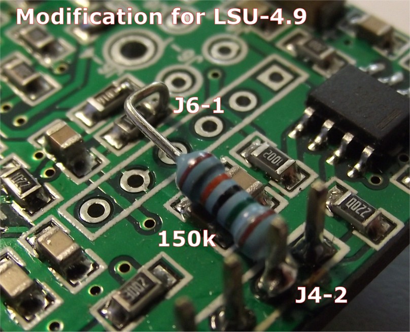
Using an LSU-4.9 sensor (rather than LSU-4.2)The default configuration for the OEM6 module is for the LSU-4.2 but it can also be ordered for the LSU-4.9, and will be delivered as described in these paragraphs. The OEM6 can be used with the LSU-4.9 with a simple modification, and updated firmware. The modification is shown here in detail showing a single ¼ watt 150kΩ (through hole) resistor wired between J4-2 and J6-1. Specifically, the J6-1 connection is actually to R25 (1k = "1001") resistor pad beside the J6-1 (Vs) hole. The connection to +5V is actually to the extended pin 2 of J4. Remember also that updated firmware must be reflashed in (this will have been done if you order the LSU-4.9 version). Refer to following sections on how to communicate with the OEM6 module for this firmware upgrade. The correct firmware is under the 2J2 section here |
Wideband Output WBlin & 5V Power (on J4)
A synthesised linear WBlin voltage is provided on J4 which also carries the 5 Volt power for the processor.
WBlin is produced by the onboard microcontroller using a PWM A/D converter
(with single pole filter). It has an effective resolution of around 9.5 bits and a fairly slow settling time.
Other Tech Edge controllers use a more accurate 12 bit hardware DAC for more-accurate/faster performance.
The DAC is one of the major differences between 2J/OEM6 and other Tech Edge controllers.
2J1's WBlin can output a maximum of 5.00 Volts and can be re-programmed for any range from λ = 0.6 to free-air (21% oxygen). The default λ to V mapping is shown at right. To convert WBlin to an AFR, simply multiply the measured voltage by 2 and add 9. The advantage of a linear output is that it's easy to write a conversion function from the wideband voltage to AFR. Note that to convert the graph to λ, use λ = AFR/14.7, or λ = (2*V + 9)/14.7. * Note-2: Remember that WBo2 is a Lambda meter and is "calibrated" to read AFR for fuels with a stoich AFR value of 14.7 (ie. "unleaded"). For other fuels that don't have a stoich value of 14.7, the x-axis (AFR) of the graph shown here should be modified. * Note-3: while the WBlin output is accurate, the Lambda data in the UART data frame (see next section) is inherently more accurate and does not suffer from some possible sources of signal degradation that beset all analogue data. |
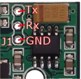
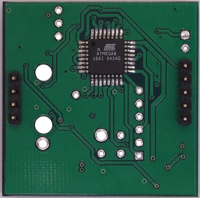
Serial Input/Output - UART Tx & Rx (on J1)The OEM6 module does NOT have an RS232 driver chip (such as the MAX-232, ST-202, HIN-202, etc.). However the microcontroller UART is still active, and it handles the bi-directional serial data stream on Rx and Tx and these signals are available on J1. Note that J1 is not marked on the PCB but its location is shown in the image - J1 is near the top right of the PCB. The actual data stream is described here and it contains a digital representation of the measured Lambda. 
There is a simple way to convert the UART signals to RS232 signal levels. The schematic below shows half of an HIN-202 TTL/RS232 transceiver chip doing this. Other transceiver devices can be used, and many have the same pin-outs. The RS232 signals are connected to a standard RJ45 socket that Tech Edge uses for all it's controllers. Of course it's possible to connect the RS232 signals to a DB9-S (female) socket for direct connection to a PC - in this case: 

The diagram at left shows the wires within the RJ45 to DB9-S data cable and also the connections at each end. Note the pin names change from left to right - the WB unit's Tx pin transmits to the PC's Rx pin (and vice versa). DB9-p5 is the shield for the Rx and Tx data lines as well as being the return data path. |
|
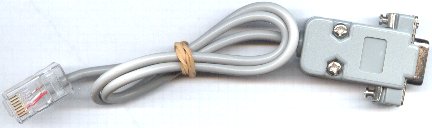
Here's an image of an early model RS232 cable for connection between a PC and the WB unit. The cable is used for either logging to a PC, or for re-flashing its code (under control of a PC). If you need to extend the cable then a standard straight through male-female DB9 extension cable should be used (ie. not a cross-over or null modem cable). Latest data cables have moulded ends. |
|
Analogue Inputs USER1 & USER2As noted above, while the 2J1 has two user inputs, the 2J-OEM6 unit does no have any input circuitry to condition these inputs. |
Pulse Inputs - RPMLO and PULSEVSSWhile the 2J1 has two pulse/RPM channels the 2J-OEM6 uni does not have any input conditioning circuitry. |
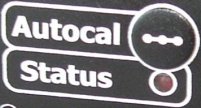
Auto Calibration
|
Diagnostics from the STATUS LEDThe 2J1 design incorporates a single RED Status LED that flashes while the sensor is warming up, and to indicate error conditions. It should be solid RED to indicate normal operation. Described here are other status conditions the LED can indicate:
This condition can occur during starting or when there is excessive battery drain during idle. It may be an indication of a poor battery or alternator/regulator, or connection to the wrong point of the vehicle's wiring. Unlocked PID : It's possible for transient conditions to cause the STATUS LED to flash OFF briefly, this is an indication of a PID unlock condition.A PID unlock is not necessarily an error, but it does indicate either very rapid changes in heating or cooling of the sensor, and/or rapid changes in the ambient air-fuel ratio. If this occurs without an explanation (such as rapid changes in throttle position) then it may be an indication of an intermittent somewhere in the wiring, or an ageing sensor. Both the LD02 and the TEWBlog logger indicate these conditions. The heater PID sharp single OFF flash is shown. This condition may indicate the sensor is positioned where it is either too hot or too cool. We have information on sensor placement. Remember wideband sensors cannot cool them self, only heat!
Auto-Cal - Automatic Sensor Re-calibration)
Calibration is the process of making the unit read as accurately as possible. Calibration is required because 2J1, although we ship it calibrated to the sensor purchased for the unit, it is manufactured un-calibrated. We do this so 2J1 can work with a number of different sensor types (it is possible to change the 7057/7200 sensor connector, at the end of the cable, for another LSU 4.0/4.2 connector). Note, we don't ship 2J1 with the 6066 connector, as shown in the image at right. Additionally, each sensors is manufactured slightly differently, and calibration matches the sensor to the unit. In fact, because Bosch sensor have a neat inbuilt calibration resistor that our units work with (see image at right), once a sensor is calibrated, very good accuracy is maintained when another sensor of the same type is substituted. So, the major reason for having a calibration function is to initially calibrate the unit to a sensor, and then to account for any ageing of the sensor (or control unit) that affects its calibration. The Auto-Cal function makes it easy to re-calibrate a sensor. In fact it almost makes it too easy! To explain this we need to look at how calibration works. Basically the sensor must be placed in a known concentration of oxygen (and/or fuel) and the "gain" of the controller adjusted to match the sensor's output. The sensor's environment is critical for it to calibrate correctly. We choose to place the sensor in free-air which means the sensor is directly exposed to fresh, clean, normal air that anyone could breath (ie. it is not sitting in an exhaust pipe) We make these assumptions about free-air :
If any of these conditions are significantly different, then, although the sensor will calibrate to some value, it will not be as accurate as possible. The basic risk for a sensor placed in an exhaust system, and with an Auto-Cal function, is that re-calibration could occur with the sensor in a "dirty" atmosphere. It is vitally important that any re-calibration occurs with the sensor out of the exhaust pipe
Further InformationWe update 2J1 documentation from time-to-time in response to your Feedback. Right now (see the latest update date below) we have more information to add, so if there's something you're keen to get more info on, then see the link below. You may be interested in our displays. Go here for more info. Images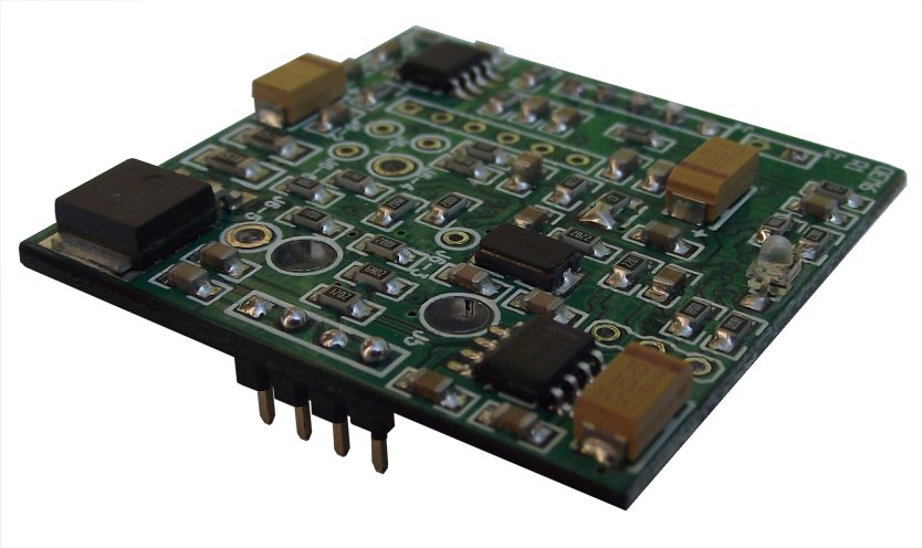
engineering mechanical diagrams. component placement diagrams. |
 The Lambda sensor requires a high current supply to maintain its heater temperature within operational limits.
This current is controlled (using PWM techniques) by the OEM6 module according to strict Bosch specifications.
J5 is on the "top" of the module, and has four pins carrying two signals:
The Lambda sensor requires a high current supply to maintain its heater temperature within operational limits.
This current is controlled (using PWM techniques) by the OEM6 module according to strict Bosch specifications.
J5 is on the "top" of the module, and has four pins carrying two signals:

)
)
)
)