 This 2Y2 document is in the process of being updated from the 2Y1 instructions to the newer 2Y2 info.
Tech Edge apologises for the delay in organising this documentation.
Make sure you refresh this page if you are expecting to see some changes:
(some browsers will do this automatically if you close-down and re-start the browser).
This 2Y2 document is in the process of being updated from the 2Y1 instructions to the newer 2Y2 info.
Tech Edge apologises for the delay in organising this documentation.
Make sure you refresh this page if you are expecting to see some changes:
(some browsers will do this automatically if you close-down and re-start the browser).
It's important to appreciate that the basic 2Y2 (ie. without the display option) is very much like the original 2Y1 with fairly minor changes to the PCB
to fix some small problems and deficiencies. Sadly, we didn't get it exactly to our liking, and made some last minute
changes to the firmware that will necessitate minor changes to the PCB.
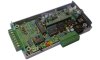
2Y2 Overlay - Part & ID diagram (2Y2 1.0c PCB)Previously we provided separate component-designation (eg. C1, R22) overlays and component-value (eg. 100nF, 220k) overlays. The 2Y2 overlay GIF image here (or see the PDF below) includes them both on the one diagram. Note: the optional on-board display area is in the light green area around U3, U4 and U7 - none of these parts is provided in the basic 2Y2 kit but come with the optional 2Y2-display-kit. |
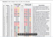
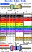
2Y2 Parts List + Resistor ChartAll parts on the PCB can be located from the 2Y2 PCB overlay + parts list PDF where the "@" column shows the grid-reference of each part in A1 format. The "Sh" column is a reference to the numbered schematic page in the on-line Schematic Guide (use the index at the start of the document to skip to the schematic description). We also have a Resistor Colour code page that may be useful if you're not that familiar with reading resistors. |
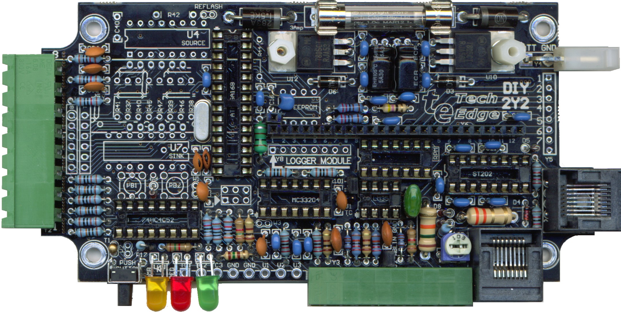
Images of finished 2Y2 PCB (without fixes)Here's the standard (non-display) version Special note: This image is missing the required modifications (for both the display and non-display versions) for the status LED described in the next section. |
Status LED Changes for Non-Display versionWe didn't quite match the display schematic with the PCB layout (This is described here). The Red status LED in particular is incorrectly routed on the PCB and a fix must be made for both the non-display and the display version. 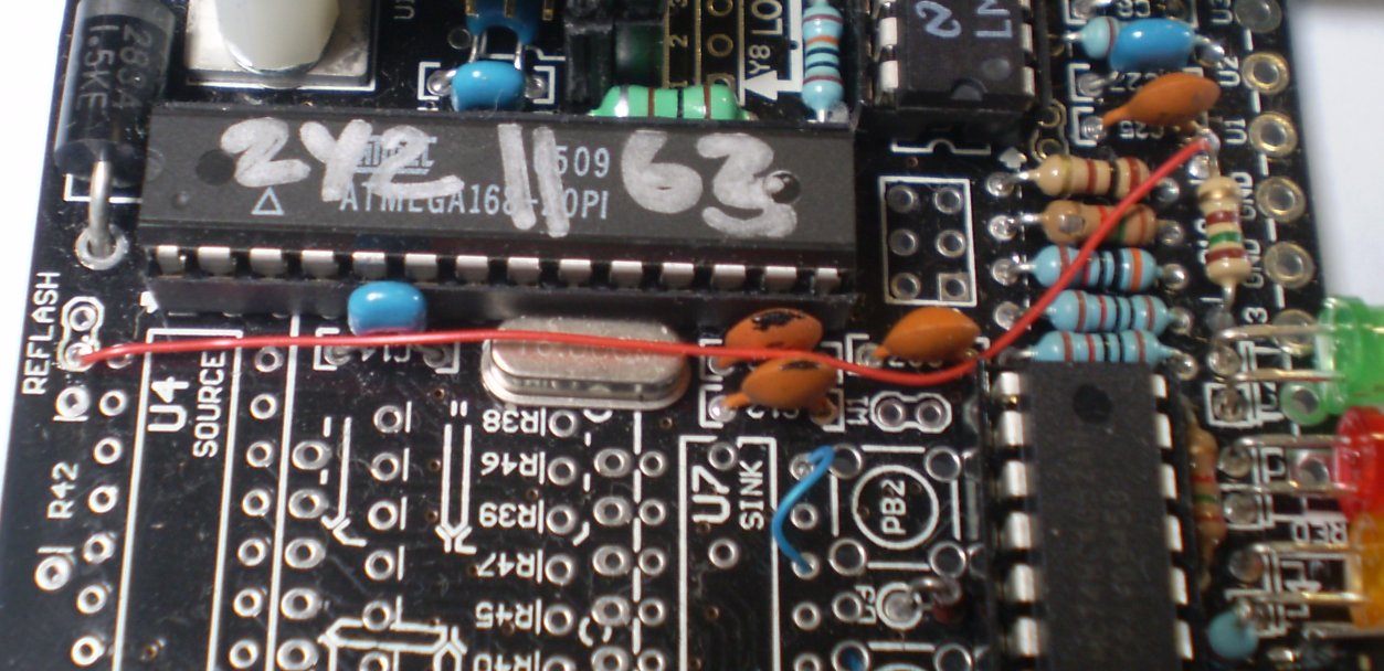
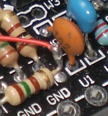
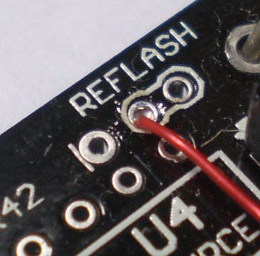
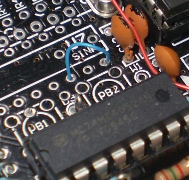
Non-Display version changes for Status LED : This change is easily made using the thin (wire-wrap) wire supplied with the standard 2Y2 DIY kit. To highlight the changes, in the images here, we have used two colours (red and blue) as there are two wires that must be added. Firstly the RED wire : this connects the right end of R19 to the left side of the REFLASH header note carefully that the right end of R19 is NOT connected to the right PCB hole intended for it. This change moves the LED drive signal from +5V (right end of R19) to the CPU's LED (PD3) signal (found on the REFLASH jumper). Secondly the BLUE wire : a short wire, simply bridges pins 14 and 16 of U7 (remember that U7 is the ONLY chip oriented "the wrong way" so look at the images for clarification). This change grounds the cathode end of the Status LED via unused U7's DRN6 pin. Display version Option and changes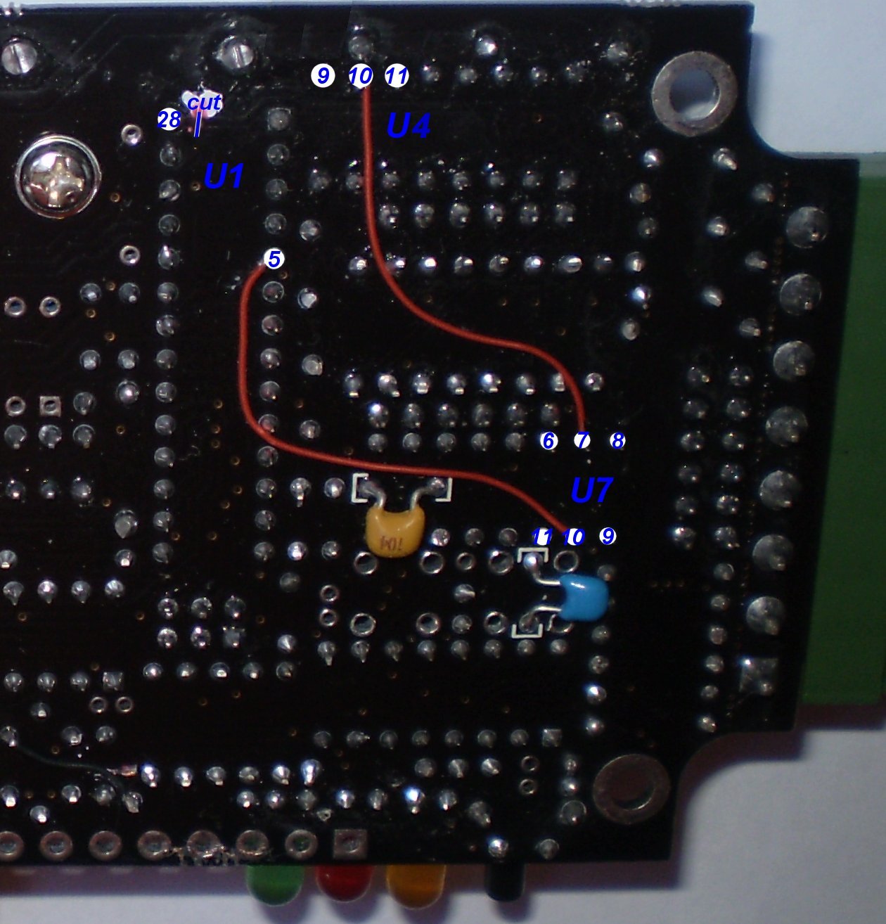
For the display-version you would have received the extra parts, including driver chips U4 and U7 and the display module itself. Additionally, new firmware must be loaded into the existing Mega-168 processor after the following changes are made. If you are modifying a working non-display 2Y2 to add the display function, then the changes outlined in the above paragraph must be reversed, in particular the right end of R19 must be soldered to the PCB after the red wire is removed. Also, the blue wire is discarded when the socket for U7 is soldered. All of the display-version changes to the PCB are made at the rear (ie. solder side) of the PCB shown enlarged here. There are three changes - a track must be cut, and two links (both shown in red in the images) made. First - Cut E2SD track : The PCB has been set up incorrectly to use the E2SD signal from pin 28 of U1 to control the display. Locate pin-1 of U1 (the Atmel CPU) - pin-1 is the pad with the square outline - Pin-28 is directly opposite. The PCB trace from pin-28 must be cut close to the circular pin-28 pad. We suggest you use a brand name Stanley knife (rather than one of these low cost sharp plastic handled knives better suited to cutting paper) and make sure the track is fully cut through without any surrounding traces being cut. You can test that the track is indeed cut by making sure there is NO continuity between U1 pin-28 and U7 pin-10. Second - Replace E2SD with (old) LED drive signal : a wire is added from pin-5 on U1 (the CPU) to pin-10 on U7. (this is the "lower" wire in the image) last - Add a missing connection : a wire is added from pin-7 on U7 to pin-10 of U4 (this is the "upper" wire in the image) Updated HXF Files for 2Y2 Display version - 23 Nov 2012The HXF file shipped with the 2Y2 kit will normally be for the non-display hardware and for the LSU-4.2. This default hardware build of the 2Y2 is functionally identical to the 2Y1 and uses the same 2Y1 HXF files found here. The display version of 2Y2 controls the status LED differently compared to the 2Y1 and the following table contains the required 2Y2 HXF files.
Remember that the WButil software program allows you to perform many functions including reading the firmware version number, free-air calibration, and reflashing (updating) the firmware version. Remember also that 2Y2's Lambda module contains two jumpers that must be set according to the firmware and the actual sensor used. Mounting the Display ModuleThe actual 4-digit 7-segment display module can be mounted a number of ways, and the display-option kit includes parts for these various options. More info, and images, 22 Nov 2012.... | |||||