 In order to successfully build the 2Y1 Do-It-Yourself wideband kit, there
are a large number of electronic
assembly steps you need to perform. The primary document to read is
the 2Y1 Assembly Guide
(this is the new version, finalised in April 2011). We recommend that
you print this document, if you are serously considering construction, because
you will need to refer to it a lot during your assembly of the 2Y1 unit.
In order to successfully build the 2Y1 Do-It-Yourself wideband kit, there
are a large number of electronic
assembly steps you need to perform. The primary document to read is
the 2Y1 Assembly Guide
(this is the new version, finalised in April 2011). We recommend that
you print this document, if you are serously considering construction, because
you will need to refer to it a lot during your assembly of the 2Y1 unit.
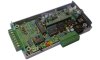
Go here for the overlay. This on-line version of the main Printed Circuit Board overlay has pop-up explanations of various parts. Just mouse over the part you are interested in.
Due to a bug in the Rev 8062 firmware, the Red Status LED did not operate as per other Tech Edge units and as described in the 2Y user manual. It flashed to indicate warmup, logging, and PID controller errors (correct behaviour), but went OFF during normal operation (incorrect behaviour). Some 2Y1 kits shipped with this version of the firmware.
This problem is now fixed! The latest 2Y firmware has restored the Red Status LED to its usual behaviour. Proceed to the firmware page, download the file and reflash your 2Y unit with the latest firmware.
The discussion above only applies to the Red Status LED. As usual, for normal operation, the Amber LED will be ON (dim or bright, depending on sensor temperature) but with a faint flicker. The Green LED should always be ON when power is supplied to the unit.
Previous constructors of the 2Y1 should be aware that there are a few errata, which they may not be aware of. That problem could be a reason why your 2Y1 is not performing well. The best way to find out about any errata is to carefully read through the 2Y1 Assembly Guide. Compare what you did during assembly to what is described in the 2Y1 Assembly Guide.
A parts list, printed circuit board overlays, assembly steps, a schematic diagram and all the known errata are given in the 2Y1 Assembly Guide. There is a discussion of some of the errata here.