Lambda Module Schematic Guide

Firmware makes it work!: The following information discusses how 2Y's pre-built lambda module works. The schematic guide for the rest of the DIY 2Y unit can be found here.

The 2Y is a professional product, albeit in DIY kit form. 2Y's performance is due in large measure to compact firmware (written in assembler) that runs at over 10 MIPS on a 16 MHz Atmel 8/16 bit RISC processor. Several man-years of work is involved in writing firmware based on the hardware described below. Tech Edge has done all the hard work for you, and the positive experience of thousands of users worldwide attests to the quality of that firmware.

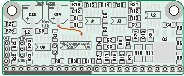
Click the image at right to get the lambda module overlay diagram (with part values and part numbers).

Connector Y1 & Y2 to Main Board's Y6 & Y7

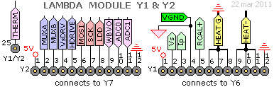
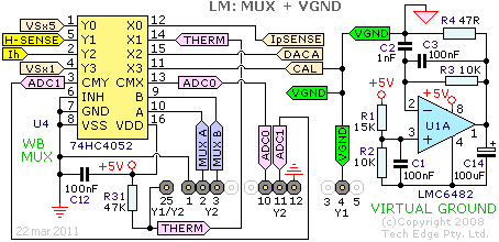
The lambda module has two connectors Y1 (on the right) and Y2 (on the left). Y1 mates with Y6 on the main board and Y2 with Y7. The heater current can be an average of several amps for short periods of time, and as the current is switched, instantaneous current can be even higher. Thus the two heavy duty traces HEATG (Heater Ground) and HEAT- (switched heater current) are kept very short, and three pins each are used on Y1 for each circuit.

Y1 and Y2 are located beside each other, and combined, have 24 pins in total. There is a 25th pin, at the left end of the combined Y1/Y2 connectir, labelled THERM. THERM carries the thermistor voltage to the MUX (see below). This is shown at the bottom left (beside R22, the 150kΩ resistor) in the overlay mentioned above.

Heater Switch, Voltage & Current Sense

High current FET (Field Effect Transistor) Q3 controls the sensor's heater circuit. Return heater current HEAT- flows through Q3 and then to the ground level point HEATG (which returns to the main board). The microcontroller's unbuffered HDRIVE signal controls Q3 in PWM (Pulse Width Modulation) fashion. Inrush current to the FET's gate is controlled by resistor R7. Resistor R8 ensures the FET switches OFF if/when the microcontroller's HDRIVE signal is tri-stated (for example, during power-up).

Heater current is measured by sensing the small voltage developed across resistors R10 & R11 that together form a 75 mΩ (75 milli Ohm, or 0.075 Ohm) high current resistor. R9 & C4 form a simple low-pass filter for amplifier U2B, which has a gain of (12+68)/12 = 6.67 times. The amplified voltage Ih (perhaps Vih may have been a better name?) is fed to the MUX described below. As the maximum voltage to the ADC is 5.0 Volts, this translates to 750 mV (5.0/6.67 Volts) across the 75 mΩ sense resistors, so an instantaneous current up to 10 Amps can be sensed.

Regarding power dissipation, at an average heater current of 2 Amps, which is a common maximum operating current, the voltage across R10//R11 is 150 mV and the power dissipated by each resistor is 0.15 * 2/2 = 150 mWatt. This is within the power rating of these resistors. The main board's 3 Amp fuse should protect these resistors during a fault condition. Q2's ON resistance at 10 Amps is less than 25 mΩ, just 250 mWatt is dissipated at this current, and less at normal operating currents, so just a small heatsink area is needed for this part.

R5 & R6 constitutes a ¼ divider, and the resulting voltage H-SENSE is fed to the MUX described in the following section. The main board also has a similar voltage divider which is used to measure H+SENSE which is the voltage at the positive end of the sensor's heater. Knowing these two voltages, and the heater current (from Ih), allows accurate measurement of the heater's impedance. This information is used during the heater's warm-up phase and to vary the power to the heater, thereby taking into account any supply voltage fluctuations, to the controller itself. After the warm-up phase, a PID (Proportional Integral Derivative) controller is activated (in software) to maintain the sensor temperature at the correct level. Note: For Bosch LSU sensors, the heater PID control variable is the internal impedance of the Nernst sense cell, known as Ri. This gives more accurate sensor temperature control. For NTK UEGO sensors, the heater impedance is the control variable to the heater PID controller, which is less accurate.

MUX & Virtual Ground Generator

Dual 4-to-1-line multiplexer (MUX) U4 (74HC4052) allows eight analog signals to be sensed, on the two microcontroller ADC input lines ADC0 & ADC1. The MUX's Y section (left) reads heater and Vs sense cell voltages (x1 and x5 versions). The MUX X section (right) reads Ip (pump current), two reference voltages and the thermistor voltage (the thermistor is located on the main board).

The schematic also shows the virtual ground generator. This provides a reference voltage VGND, 2 Volts above GND, the real ground level. VGND goes to the common terminal between the pump cell and the Nernst cell. Resistors R1 & R2 divide the +5 Volt power supply line down to 2.0 Volts. Op-amp U1A is a high speed buffer, and along with capacitor C14 which provides short term charge storage, provides a stable, relatively high current VGND. Because the absolute level of VGND is vitally important to the firmware's operation, the CAL input to the MUX allows internal run-time calibration to take place. Similarly, the DACA input to the MUX serves to calibrate the 12-bit hardware DAC's output.

Vs Amplifier, LSU 4.9 Bias Current, LSU/NTK Select

The Vs Drive (VsDRV) signal, along with a lot of measurements and calculations, is used as the basis of measuring the Bosch LSU's sense cell's impedance (Ri). For accurate Lambda measurements the temperature dependant sense cell must be held at a constant temperature, and a measure of its temperature is Ri.

The NTK UEGO sensors have different operating characteristics to the Bosch LSU, so a different mechanism is employed for maintaining constant cell temperature. The jumper J3 selects one of two resistor values that are in series with the Vs drive scheme.

The LSU 4.9 is a newer sensor than the LSU 4.0 (6066) and LSU 4.2 (7057, 7200, etc.). It requires a bias current that is supplied by R22.

The raw Vs signal from the sensor is low-pass filtered by R25 & C8 where it becomes VsX1 and is read by the microprocessor's ADC1 line via the MUX U4 Y section. Note that as the sensor's Vs/Ip point is at a 2.0 Volt offset above GND, the stoich point as measured by VsX1 is ≅ 2.45 Volts.

Op-amp U3A level shifts the Vs input relative to VGND and amplifies by a value determined by the 4 resistors R26 to R29. The gain is for a non-inverting op-amp with a non-inverting negative reference. With the resistor values shown, the gain is 150/30 = 5. The level shifting function also shifts this to the complete range of 0 to 5 Volts. Thus, a 450 mVolt input on Vs (relative to VGND) will produce an output of 5.0*0.45 = 2.25 Volts on VsX5.

12-bit DAC, WBlin Buffer, IP Drive, IP Sense

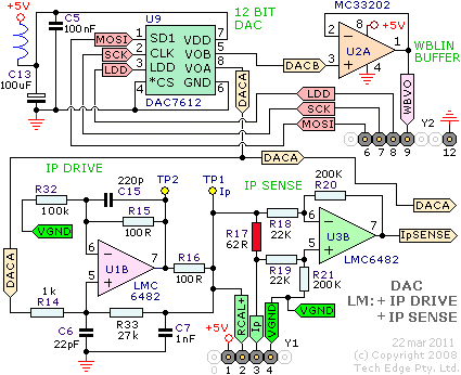
The DAC (Digital to Analog Converter) U9 is a high quality 12-bit DAC with an internal voltage reference. The DAC is used to generate the Ip drive voltage DACA (described below) and the linear wideband voltage DACB, which is buffered by the unity gain op-amp U2A, then passes out of the module as WBVO. The DAC is controlled by the three microprocessor signals LDD, SCK, & MOSI, which are on connector Y2.

DACA is buffered by an amplifier circuit built around op-amp U1B, five resistors and three capacitors. This circuit generates the pump current Ip that goes to the sensor pump cell (via the red 62 Ω resistor, then out through the Controller-to-Sensor cable).

Pump current across the (red) 62 Ω resistor R17 is accurately sensed by differential amplifier U3B. Both R17 and the calibration resistor (in the sensor's connector) are connected across the sensor's Ip and RCAL points. Thus the sensor may be changed without doing a free-air calibration, but this only gives reasonably good accuracy. A proper free-air calibration is needed for better accuracy.

The three signals DACA, IpSENSE & CAL (that is, VGND) go to the MUX (above) and are all used by the microprocessor to calculate the normalised pump current which is used to calculate the digital Lambda value.

External References