The 2Y1 unit does NOT use U2, U4, nor U7. These ICs were to be used for options that are now not offered. They may be deleted from the main PCB in a future board revision.
)
Lambda Module PinsAlthough the pre-built lambda module comes tested and 100% functional, some early kits did not have the 25 gold header pins soldered on. Refer to the images to ensure the pins are correctly soldered on. Click here to see other views. The main board also uses a 25-pin socket made up of a strip of 24 pins and a 25th pin shown here. Some later kits erroneously included an extra 25 male header pins, in the form of a long strip, even though they were no longer required to complete the lambda module. Please ignore any such strip if your kit includes it. |
)
Thermocouple Inputs Read IncorrectlyThere was an error in some early component lists. The feedback capacitor C36 (around the thermocouple amplifier U8C) shown at right, designed to prevent noise pickup, was originally specified with a relatively large value (1 nF). The capacitor stores charge as the thermocouple mux switches between channels. This has the effect that all thermocouple channels (and the logger button) bleed through and the actual thermocouple value read is an average of all the inputs. The solution is to simply remove R36 as the circuit is still stable without this capacitor. The best way to remove C36 is to snip it in half with sidecutters and to then individually remove each half with soldering iron and long-nose pliers. Here is a combined schematic for the mux & thermocouple amplifier. The latest 2Y1 Assembly Guide does not specify that R36 is ever installed, so this problem has now disappeared. |
)
No PC logging, or Display shows "nd"Symptom: There is no RS232 communication to attached Tech Edge displays or to an attached PC. When a Tech Edge display is showing "nd" (for "no data"), that means that it has detected no logging frames. This can be caused by a failure of RS232 communications between the unit and the display. There is an error on the Rev 1.0b PCB - on the underside (solder side) of the PCB you should connect a wire between U5 (ST202/HIN202) pin-15 and GND as per the RS232 driver schematic. This is best done with a wire from U5-p13 (GND) to the adjacent capacitor leg that goes to U5-p15. Click on the image to enlarge. These instructions are included in the latest 2Y1 Assembly Guide, so this problem has now disappeared. |
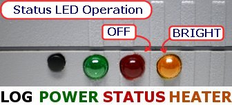
Red Status LED IncorrectDue to a bug in the Rev 0862 firmware, the Red Status LED did not operate as per other Tech Edge units and as described in the 2Y user manual. It flashed to indicate warmup, logging, and PID controller errors (correct behaviour), but went OFF during normal operation (incorrect behaviour). Some 2Y1 kits shipped with this version of the firmware. This problem is now fixed! The latest 2Y firmware has restored the Red Status LED to its usual behaviour. Proceed to the firmware page, download the file and reflash your 2Y unit with the latest firmware. The discussion above only applies to the Red Status LED. As usual, for normal operation, the Amber LED will be ON (dim or bright, depending on sensor temperature) but with a faint flicker. The Green LED should always be ON when power is supplied to the unit. |
)
)
)
)
)