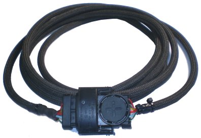
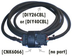
At right is an image of the finished extension cable - designed to extend a Bosch 6066 sensor.
As with some images in this document, click on the image to see an enlargement, in this case, showing just the two connectors.
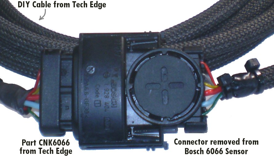
The left connector is available complete with terminals and seals from Tech Edge as part [CNK6066].
At right is the connector from the end of the 6066 sensor we'll modify.
Removing and Modifying the 6066 Connector
Firstly cut off the connector from a donor 6066 sensor
 (we assume you use a "dead" 6066 sensor).
Make sure you leave several inches (say 100 mm) of wire because later you'll need to grip each in turn to release the wires with terminal pins and seals that will be re-used.
Note the wire is made from hard stainless steel (not soft copper),
so make sure you have good quality side cutters that will not be damaged when cutting through such hard metal.
(we assume you use a "dead" 6066 sensor).
Make sure you leave several inches (say 100 mm) of wire because later you'll need to grip each in turn to release the wires with terminal pins and seals that will be re-used.
Note the wire is made from hard stainless steel (not soft copper),
so make sure you have good quality side cutters that will not be damaged when cutting through such hard metal.
The circular cover on one side of the connector must now be unscrewed (see image).
Two crossed screw drivers, placed in adjacent slot holes, will unscrew the lid.
This reveals the calibration resistor (called RCal) that is unique to our (dead) sensor.
RCal has been laser trimmed at the factor and will only be valid for the sensor you have just cut off.
We must unsolder and discard the existing RCal part.
RCal adjusts the sensitivity of each sensor so the sensor may be used with devices that don't have free-air calibrating facilities (ie. it works out-of-the-box).
Note the laser-cut part of the film of carbon deposited onto the ceramic base of the RCal part - more cutting means larger resistance).
|
Removing the Sensor Connector's Pins
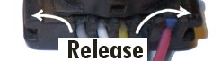
Firstly remove the rear plastic black cover over the wires at the back of the connector (arrows point to the release tabs).
This cover is a secondary measure to retain the wires should the retention ears fail, but must be removed before the pins can be removed.
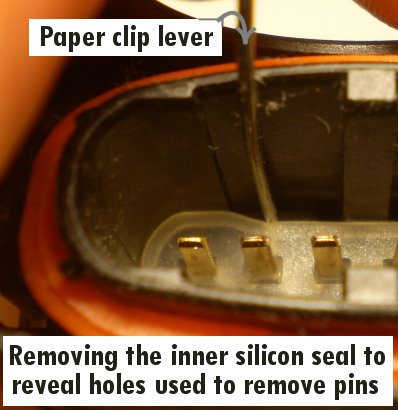
The image at left shows how to remove the clear silicon-rubber seal sealing the pins within the sensor connector.
Use a small paper-clip with a 2mm right angled (ie. "L" shaped) section at the end.
Slide the paper-clip tool past the edge of the seal and gradually pull all of the seal up, working your way around, a small bit at a time.
We'll re-use the seal, so don't be too rough, it may take a minute or so to get it out, but it's a press fit, and readily removed.
Now to remove the pins - please note that the pins are held by spring pressure and once the spring is released, they will slide out.
Using force on them will deform the surrounding plastic-well they grip into and this and will lock them tighter
- in fact, it may help to push the pins in further while releasing the retention ears (which are the springs mentioned above)!
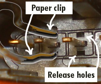
The image at right shows another formed paper-clip tool being used to release the pins' retention ears.
Locate the release holes shown above and below each pin in the image.
To see what is required to release the pins, find an image of the removed pins and seals shown below left.
The pins' retention ears must be depressed (by accessing the release holes) with the specially formed paper-clip tool.
Once depressed, the wires with pin and seal attached, can be pulled gently out the back of the connector body.
Note that both ears must be released at the same time, so the paper-clip should be bent to have a tweezers shape.
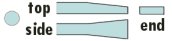
We flattened the paper-clip ends slightly (see profile image at left) with a hammer and anvil (or use the flat bit found on the back some vises).
|
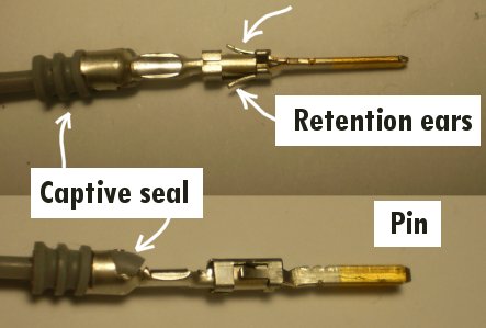
Pin, & Spade Terminal, Details
These two images show details of the pins that must be removed.
Note (at left) the wire seals are held captive by the rear part of the pins.
The retention ears positively lock the pins into the connector - they will produce an audible click when inserted past the retention ridge in the connector.
For removal, the pins must be depressed so they can be slid past the connector's (plastic) retention ridge.
Too much removal force may force (and lock) the ears into the retention ridge - thought and patience is required!
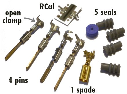
At right can be seen we have opened up the seal retention part of the pins and released the four grey, and one larger blue, silicon seals.
Note carefully that the red wire (pin 1) with the blue seal has a spade terminal
(the corresponding pin is moulded into the connector) and the spade terminal has just one release tab
(and the connector has just one release hole for this pin too). We used a larger paper-clip to release the spade terminal.
Also shown is the RCal part we previously removed - we do not re-use RCal.
|
Modifying The 6066 Connector's RCal Circuit
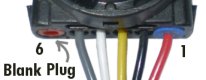
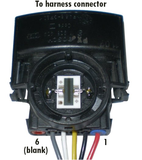
You will note that the sensor itself has five (5) wires that go into the connector, but the connector has six (6) pins.
The sixth pin connects to one end of the RCal resistor (the other end of RCal goes to Ip - the red wire on pin-1).
Now, note carefully that the 6066 connector has a red blanking plug as shown at right.
Removing this red plug reveals a small (but incomplete) drilling into the connector.
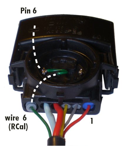
We must now drill further into the connector and then make a cross-drilling into the area that previously contained the RCal part.
The idea is to run a wire (the green one) into the back of the connector, solder this to the left hand RCal post,
and then this post connects through to pin-6 at the front of the connector.
This is shown, in the form of hidden parts, shown dotted, in the image at left.
Cross Drilling
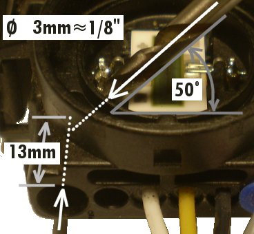
One way to drill the holes for the green wire (RCal extension) is described pictorially at right.
We used a 1/8" bit (say 3mm) in a low speed drill and first drilled no more than 13mm (1/2") into the back of the hole for wire-6,
We then cross drilled from behind RCal (in this photo we had not taken out RCal first!) at an angle of about 50°
until we reached our first hole. We made sure there was no swarf in the holes.
Just be careful not to damage the holes where adjacent pins are inserted.
A (green) wire must be able to go into the end hole and bend up into the RCal cavity
where it connects to the adjacent pin (that was soldered to the RCal part).
Note that we used a grey seal (from a 6066 connector kit) to complete the RCal connection -
we had a spare because the new large red and large light-blue wires (connector pin-4 and pin-5 in the image at left)
for the heater circuit were too large to use the seal from the original wires.
|
Re-pinning the 6066 Connector
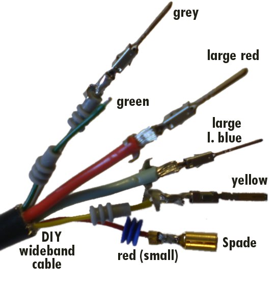
The image at right shows the wires before we inserted them into the connector.
(The previous image immediately above left shows the result; ie. after inserting them into the connector).
Note how the seals are not yet mechanically crimped into the terminals (remember how they appeared here).
You will also note that we actually soldered a short length of wire (not shown) to the green wire in order for it to be long enough to reach the RCal post in the RCal cavity.
Buying Parts
Tech Edge does NOT sell the 6066 connector that comes with the 6066 sensor.
We do sell the parts shown at left.
The harness connector [CNK6066].
We sell two high quality fibreglass sheathed DIY cables that can be used between the two connectors:
a 2.6 m (~8.5 feet) [DIY26CBL]
and 4.0m (~13 feet) [DIY40CBL].
Tech Edge also sells the Bosch 6066 LSU 4.0 sensor as part
[006066]
although this has now become a relatively expensive sensor because it is effectively a legacy part.
|
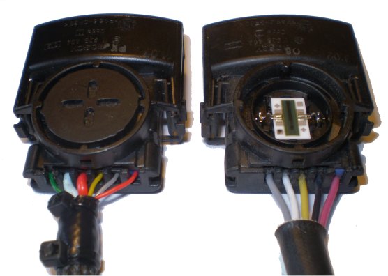
At right is shown the before (right) and after 6066 sensor connector.
Replace the 6066 with the 7200?
The difference between the 6066 LSU-4.0 and the 7200 (or 7057) LSU-4.2
sensor is an operating current (Ip) difference of about 20%.
Most modern controllers that have a free-air calibration facility and use a 6066
will also allow a 7200/7057 to work successfully too (the free-air calibration facility should be able to factor the 20% difference).
If you have a controller with a 6066 harness connector then it may be a simple matter to replace the connector with a
new 7200 harness connector - we sell these connectors as part [CNK7057].
We also sell the 7200 Bosch LSU 4.2 sensor as part [007200].
We welcome corrections and feedback to this document - use the feedback link below (it will automatically fill in the subject and email address).
|
|
 extension cable by re-using the end of "dead" 6066 sensor.
It focuses on how to remove and modify the 6066 sensor's connector.
The technique is applicable to making extension cables for different Bosch (and other manufacturer's) cables.
The full Bosch part number for the 6066 sensor is 0-258-006-066,
and you can find more information about Bosch sensors here
extension cable by re-using the end of "dead" 6066 sensor.
It focuses on how to remove and modify the 6066 sensor's connector.
The technique is applicable to making extension cables for different Bosch (and other manufacturer's) cables.
The full Bosch part number for the 6066 sensor is 0-258-006-066,
and you can find more information about Bosch sensors here