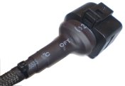
 In mid 2007 Tech Edge improved the way it manufactures cables.
They should now be more reliable, stronger, and less prone to damage through flexing in the middle and at either end.
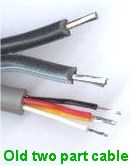
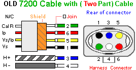
We previously used two individual cables with a sheath to hold and protect them both.
Now we use a specially manufactured single cable with different sized conductors and the sheath is used to just protect the cable.
A complication is that the colours of the cable's internal wires changes slightly between the two systems.
LSU (5 Wire + RCal) Pinouts
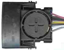
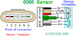
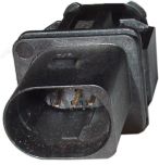
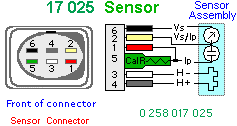
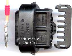
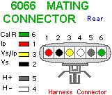
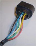
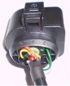
All LSU sensors we have seen, regardless of the connector, use the five lead colours shown in the image below (Red, Yellow, Grey, Black, White). The laser trimmed calibration resistor (Rcal) is unique to each sensor and adds a sixth pin to the connector. Each sensor's Rcal (shown as 30-300Ω) has a unique value that only works properly with that sensor. Rcal connects internally to the Pump Current (Ip) sensor lead.
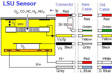
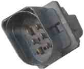
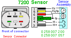
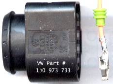
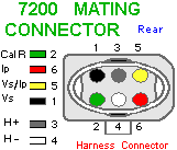
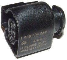
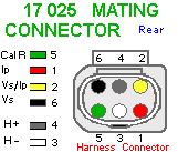
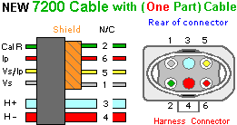



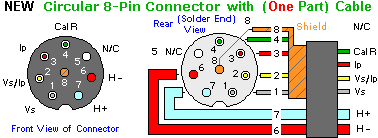 New (One Part) Cable : This diagram shows both the front of the circular 8-pin connector as seen by someone looking at the end of the completed cable,
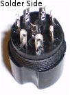
and also the wire or solder-side end of the connector that will be seen during construction or repair.
Note that the shield (braid) is connected to the centre (pin 8), but at the sensor end of the cable, the braid is left unconnected -
thus the braid acts as a
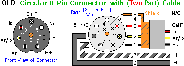 Old (Original Two Part) Cable : This diagram shows the corresponding two part (older or original design) cable.
All the signal wires are carried in a cable with four individually shielded small wires.
The Heater current is carried in a separate heavy duty figure-8 cable that goes to pins 6 & 7
Note : the heater wire with tracer colour goes to pin 7.


