 This is the LA1 User's Guide or operating manual for the LA1 display.
LA1 is field re-programmable, and from time to time this document may be update with information
on features that may have been added.
This is the LA1 User's Guide or operating manual for the LA1 display.
LA1 is field re-programmable, and from time to time this document may be update with information
on features that may have been added.
To buy the LA1 go to the LA1 main page.
|

The most common problem users experience is the nd, or no data, display as shown at left. It's caused when LA1 doesn't see data from WBo2. The solution is described below. |
The following information relates to LA1 firmware version 0229 or above. In the descriptions of the various displays, view names are shown in bold blue. Note: after re-configuration, some of the default behaviour detailed below may change. The default view is the display last saved, and is initially the AFR display.
|
|
|
|
|
|
|
|
|
|
|
Releasing the left (A) button shows the currently selected view.
The default view cycled through are |
|
|
|
|
|
|
|
|
|
|
Sensor Heater Faults - Other heater faults that are detected by WBo2 include :
|
|
A PID unlock is not necessarily an error, but if a PID unlock condition occurs regularly without an explanation then it should be investigated. |
Config Mode & the Reprogramming Interface Adaptor)
)
LA1 can be field upgraded with new firmware, and its display modes re-configured, using the LA1 interface adaptor (*) shown at left. How the adaptor is physically connected both to LA1, a PC, and source of power is shown at left. Power is obtained from WBo2's two pin power cable, or a 12 volt power supply is used. Click on either of the images for an enlarged popup, or for the programming schematic here. Note (*) see here for info on the old interface adaptor. The WButil flash program can be used to update LA1's firmware, remembering that the LA1 must be in config mode for correct reflashing.
|
Rescue Reflashing)
For the very rare occasion when the LA1 seems dead (perhaps after an unsuccessful reflash, or a reflash with the wrong .HXF file) it may be necessary to perform a rescue-reflash. This requires access to the LA1's electronics. Begin by removing the two screws securing the case's back. Pull out the electronics and rotate so you see the view at left (click image enlarge)
Note that you may have to first rescue re-flash the code in (select the Flash Only? check box), and when that has completed, remove the rescue re-flash shunt and then select the EE Only? check box and flash in the EE data (of course remembering to hold down the A button during LA1's power-up to enter the correct mode). Yes it sounds complicated, but a rescue re-flash is a last ditch option that's not normally used unless drastic action is required. |
The WButil program provides support for LA1, and is used to change LA1's default behaviour and the display functions. There are two ways to program; either from scratch or by applying a pre-configured HXF file. Various HXF files have been produced by Tech Edge to handle the most common uses for the LA1 display including single and dual channel configurations.
This section will be updated when the PC based configuration options (in the CONF.exe program) for LA1 are completed.
Note: this document is subject to updates ....
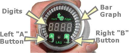 The major elements of the LA1 display are shown at right.
The two press-buttons are called the left or A and right or B buttons.
The four characters of 7-segment display are called the digits,
and the 30 element array of bars is called the bargraph.
The small oval window immediately below the digits allows light to fall on an
LDR (Light Dependant Resistor) which senses the ambient light intensity and adjust the display's intensity to match.
The major elements of the LA1 display are shown at right.
The two press-buttons are called the left or A and right or B buttons.
The four characters of 7-segment display are called the digits,
and the 30 element array of bars is called the bargraph.
The small oval window immediately below the digits allows light to fall on an
LDR (Light Dependant Resistor) which senses the ambient light intensity and adjust the display's intensity to match.
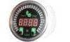
 Pressing the left (A) button cycles through the four possible display views
which are numbered 0 through 3.
While the left (A) button is depressed,
The number of the view that will be shown next is
displayed in the left digit position - as shown at left.
Pressing the left (A) button cycles through the four possible display views
which are numbered 0 through 3.
While the left (A) button is depressed,
The number of the view that will be shown next is
displayed in the left digit position - as shown at left.
 It's possible to change the default view that is presented each time the LA1 powers up.
First, select the view you want to be the new default view by pressing the A (left) button.
Then hold down the same A button for about 5 seconds
until the 4-segment display shows "n---" (see images at left) where n is the new default view.
Now unplug the LA1 and then plug it in again.
The LA1 should now power up in the view you selected.
Note: the "next" view number is displayed during the 5 second button-press, ignore this!
It's possible to change the default view that is presented each time the LA1 powers up.
First, select the view you want to be the new default view by pressing the A (left) button.
Then hold down the same A button for about 5 seconds
until the 4-segment display shows "n---" (see images at left) where n is the new default view.
Now unplug the LA1 and then plug it in again.
The LA1 should now power up in the view you selected.
Note: the "next" view number is displayed during the 5 second button-press, ignore this!
)
)