 This is the user's guide or operating manual for the LD02 display.
Because LD02 is field re-programmable, from time to time this document will be update with information
on the latest features.
This is the user's guide or operating manual for the LD02 display.
Because LD02 is field re-programmable, from time to time this document will be update with information
on the latest features.
The LD02 main page is here.
|

The most common problem users experience is the nd, or no data, display as shown at left. It's caused when LD02 doesn't see data from LD02. The solution is described below. |
The following information relates to LD02 firmware version 0123 or above. In the descriptions of the various displays, screen names are shown in bold blue. Note: after re-configuration, some of the default behaviour detailed below may change. The default screen is the display last saved, and is initially the AFR display.
|
|
|
|
|
|
|
|
|
|
|
Releasing the top button shows the currently selected screen.
The default screens cycled through are |
|
|
|
|
|
|
|
Other heater faults that are detected by WBo2 include :
|
|
A PID unlock is not necessarily an error, but if a PID unlock condition occurs regularly without an explanation then it should be investigated. |
|
Config Mode & the Reprogramming Interface Adapter)
)
LD02 can be field upgraded with new firmware, and its display modes re-configured, using the LD02 interface adapter (*) shown at left. How the adapter is physically connected both to LD02, a PC, and source of power is shown at right. Power is obtained from WBo2's two pin power cable, or a 12 volt power supply is used. Click on either of the images for an enlarged popup, or for the programming adapter's schematic here. Note (*) see here for info on the old interface adapter. The FLASH.exe program can be used to update LD02's firmware. The CONF.exe program will soon provide support for LD02, and is used to change LD02's default behaviour and the display functions.
Configuring LD02This section will be updated when the PC based configuration options (in the CONF.exe program) for LD02 are completed. Note: this document is subject to updates .... |
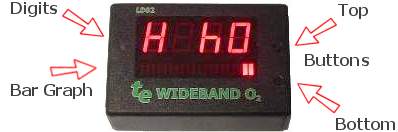 The major elements of the LD02 display are shown at right.
The press-buttons on the right side are called the top and bottom buttons.
The four characters of 7-segment display are called the digits,
and the 20 element array of bars is called the bargraph.
The small oval window immediately to the left of the digits allows light to fall on an
LDR (Light Dependant Resistor) which senses the ambient light intensity.
The major elements of the LD02 display are shown at right.
The press-buttons on the right side are called the top and bottom buttons.
The four characters of 7-segment display are called the digits,
and the 20 element array of bars is called the bargraph.
The small oval window immediately to the left of the digits allows light to fall on an
LDR (Light Dependant Resistor) which senses the ambient light intensity.
 Immediately after power is applied to LD02 the Tech edge logo screen appears.
This lasts for two to three seconds, during which time the display brightness may change to suit the ambient light conditions.
Immediately after power is applied to LD02 the Tech edge logo screen appears.
This lasts for two to three seconds, during which time the display brightness may change to suit the ambient light conditions.
 If the top button is held down during the application of power,
after approximately one second the tE screen will change
to show the current firmware's version number (0123 in this example),
and LD02 enters config mode which is further described
If the top button is held down during the application of power,
after approximately one second the tE screen will change
to show the current firmware's version number (0123 in this example),
and LD02 enters config mode which is further described  Subsequently, if the default display is either Lambda or AFR, and normal WBo2 operating conditions apply,
the LD02 display will change from tE to
the sensor heating in progress display.
Depending on external conditions, this phase normally lasts 20 to 30 seconds.
Other conditions, possibly error indications, may also be displayed briefly.
Subsequently, if the default display is either Lambda or AFR, and normal WBo2 operating conditions apply,
the LD02 display will change from tE to
the sensor heating in progress display.
Depending on external conditions, this phase normally lasts 20 to 30 seconds.
Other conditions, possibly error indications, may also be displayed briefly.
 After heating, the display will show the default screen which
is normally the AFR display shown here.
The default screen can be changed as described below.
The bargraph will move left for richer mixtures, and right for leaner mixtures.
At the extreme left or right the bar will change to
After heating, the display will show the default screen which
is normally the AFR display shown here.
The default screen can be changed as described below.
The bargraph will move left for richer mixtures, and right for leaner mixtures.
At the extreme left or right the bar will change to
 When the AFR (or Lambda) is richer or leaner than the programmed values,
either of the two rich or LEAn limit indications is displayed.
When the AFR (or Lambda) is richer or leaner than the programmed values,
either of the two rich or LEAn limit indications is displayed.
 Pressing the top button cycles through the four possible display screens
which are numbered 0 through 3.
While the top button is depressed,
The number of the screen that will be shown next is
displayed in the left digit position - as shown at right.
Pressing the top button cycles through the four possible display screens
which are numbered 0 through 3.
While the top button is depressed,
The number of the screen that will be shown next is
displayed in the left digit position - as shown at right.
 It's possible to change the default screen so this screen is presented each time LD02 is powered up.
First, select the screen you want to be displayed by cycling through the displays,
then press and hold down the top button for at least 4 seconds.
One of the 4 possible screens at left will show, for as long as the button remains depressed.
It indicates the screen number programmed as the default screen.
Note: the next screen number is displayed during the
4 second wait until the default screen number is programmed, ignore this!
It's possible to change the default screen so this screen is presented each time LD02 is powered up.
First, select the screen you want to be displayed by cycling through the displays,
then press and hold down the top button for at least 4 seconds.
One of the 4 possible screens at left will show, for as long as the button remains depressed.
It indicates the screen number programmed as the default screen.
Note: the next screen number is displayed during the
4 second wait until the default screen number is programmed, ignore this!
 When there's no communications between LD02 and WBo2, the nd or No Data screen is shown.
This screen will only be seen when LD02 is expecting frame data to display but none is sent.
WBo2 may not be connected, or WBo2 has been set up to generate the wrong type of data frames -
this can occur if an old revision of the
When there's no communications between LD02 and WBo2, the nd or No Data screen is shown.
This screen will only be seen when LD02 is expecting frame data to display but none is sent.
WBo2 may not be connected, or WBo2 has been set up to generate the wrong type of data frames -
this can occur if an old revision of the  Among the conditions that can occur during sensor warmup are
high (H bH) or low (H bL)
battery voltage.
Among the conditions that can occur during sensor warmup are
high (H bH) or low (H bL)
battery voltage.
)